场景中物体类的编写
相机
定义相机类,包含其位置,观察位置,向上方向的属性。
 1
 2
 3
 4
 5
 6
 7
 8
 9
10
11
12
13
14
15
|
class Camera
{
    constructor(
        position = [0.0, 0.0, 1.0],
        gazePosition = [0.0, 0.0, 0.0],
        viewUpVector3 = [0.0, 1.0, 0.0],
        viewPort = {width: 1.0, height: 1.0, d: 1.0}
    )
    {
        this.position = position;
        this.gazePosition = gazePosition;
        this.viewUpVector3 = viewUpVector3;
        this.viewPort = viewPort;
    }
}
|
还有获取变换到视图空间和到裁切空间的两个矩阵的方法
 1
 2
 3
 4
 5
 6
 7
 8
 9
10
11
12
13
14
15
|
//续以上类中代码
 getViewMatrix()
{
    const res = mat4.create();
    mat4.lookAt(res, this.position, this.gazePosition, this.viewUpVector3);
    return res;
}

getProjectionMatrix(canvas)
{
    const res = mat4.create();
    mat4.perspectiveNO(res, this.fovy, canvas.clientWidth / canvas.clientHeight, this.near, this.far);

    return res;
}
|
平面
 1
 2
 3
 4
 5
 6
 7
 8
 9
10
11
12
13
14
15
|
class PlaneMesh
{
    constructor(
        position = [0.0, 0.0, 0.0],
        size = [5, 5],//大小
        sub = 20,//细分等级
        rotateXYZ = [0, 0, 0]//旋转,默认朝向Z
    )
    {
        this.position = position;
        this.size = size;
        this.sub = sub;
        this.rotateXYZ = rotateXYZ;
    }
}
|
由于渲染需要面的顶点,同时想要渲染模拟水面效果需要面具有尽量多的顶点属性中定义了面的细分等级。
现在还需要一个方法可以获取面的所有顶点。
 1
 2
 3
 4
 5
 6
 7
 8
 9
10
11
12
13
14
15
16
17
18
19
20
21
22
23
24
25
26
27
28
29
30
31
32
33
34
|
//续以上类中代码
getVertexData()
{
    var data = [];
    var meshCoordSize = [];
    meshCoordSize[0] = this.size[0] / (this.sub + 1);
    meshCoordSize[1] = this.size[1] / (this.sub + 1);
    for(var i = 0; i < (this.sub + 1); i++)
    {
        var p1 = [0, i * meshCoordSize[1], 0];
        var p2 = [0, (i+ 1) * meshCoordSize[1], 0];
        var p3 = [p1[0] + meshCoordSize[0], p1[1], 0];
        for(var j = 0; j < ((this.sub + 1) * 2); j++)
        {
            data.push(p1[0], p1[1], p1[2]);
            data.push(p2[0], p2[1], p2[2]);
            data.push(p3[0], p3[1], p3[2]);

            p1 = p2;
            p2 = p3;
            if(p1[0] == p2[0])
            {
                p3 = [p1[0] + meshCoordSize[0], p1[1], 0];
            }
            else
            {
                p3 = [p2[0], p2[1] + meshCoordSize[1], 0];
            }
        }
    }

    var res = new Float32Array(data);
    return res;
}
|
以上代码生成的坐标是四边形一角放在原点,在第一象限且两个邻边对齐坐标轴,之后还要进行矩阵变换到对应position和rotateXYZ。
webgl中面按三角面渲染,顶点数据会有重复顶点。其实可以通过顶点索引数据来避免顶点数据重复,但是同样位置的顶点在不同的面可能具有不同的顶点颜色和法线,视情况而定。这里采用重复情况。
同时顶点的读取要满足三个三个构成正确的三角形,要注意顶点填入的顺序。这里参考webgl,drawArray函数绘制TRIANGLES_STRIP情况下的绘制顺序填入。

既对于ABCDEF点,先填入ABC,然后BCD,CDE和DEF共4个三角面。
html环境配置
创建canvas和获取webgl上下文
1
2
3
4
5
6
7
8
|
<body>
    <canvas id='glcanvas' width='1920' heigth='1080' style='border: 2px solid black;'></canvas>
</body>

<script>
    const canvas = document.getElementById("glcanvas");
    const gl = canvas.getContext('webgl');
</script>
|
着色器的创建,编译和链接
创建着色器资源
通过以下代码创建着色器资源
1
2
3
4
5
6
7
|
const vertexShaderSource = `
你的顶点着色器代码
`

const fragmentShaderSource = `
你的片员着色器代码
`
|
着色器创建,编译
1
2
3
4
5
|
const shader = gl.createShader(type);
//type为gl.VERTEX_SHADER,gl.FRAGMENT_SHADER
gl.shaderSource(shader, source);
gl.compileShader(shader);
gl.getShaderParameter(shader, gl.COMPILE_STATUS);
|
链接,创建program
1
2
3
4
|
const program = gl.createProgram();
gl.attachShader(program, vertexShader);
gl.attachShader(program, fragmentShader);
gl.linkProgram(program);
|
以上代码在各个项目可以多次使用,可以封装为函数写在mjs文件中。
创建渲染场景
实例化上文创建的Camera类,PlaneMesh类。如果可以也可以创建并实例化灯光类。
1
2
3
|
const camera = new Camera();
const plane = new PlaneMesh();
// const light = new Light();
|
渲染循环
 1
 2
 3
 4
 5
 6
 7
 8
 9
10
11
12
13
14
15
16
17
18
19
20
21
22
23
24
25
26
27
28
|
function draw(currentTime)
{
    gl.viewport(0, 0, gl.canvas.width, gl.canvas.height);
    gl.clearColor(1.0, 1.0, 1.0, 1.0);
    gl.enable(gl.DEPTH_TEST);
    gl.clear(gl.COLOR_BUFFER_BIT | gl.DEPTH_BUFFER_BIT);


    gl.useProgram(program);
    //变换矩阵的计算
    const m = mat4.create();
    const v = camera.getViewMatrix();
    const p = camera.getProjectionMatrix(canvas);

    const m_mvp = mat4.create();
    mat4.multiply(m_mvp, v, m);
    mat4.multiply(m_mvp, p, m_mvp);
    //配置program中着色器的uniform和attribute
    //其他配置
    gl.drawArrays(mode, first, count);
}
function render(currentTime)
{
    draw(currentTime);
    requestAnimationFrame(render);
}

render();
|
1
2
3
4
|
//示例
const uniformLoc = gl.getUniformLocation(program, "着色器中对应变量名");
gl.uniform1f(uniformLoc, 数据);
//1f为float;2f,3f和4f为vec2,vec3和vec4;Matrix4f是4 x 4矩阵;1fv加一个v是数组
|
attribute
 1
 2
 3
 4
 5
 6
 7
 8
 9
10
11
12
13
14
15
16
|
//示例
const positionBuffer = gl.createBuffer();
gl.bindBuffer(gl.ARRAY_BUFFER, positionBuffer);
gl.bufferData(gl.ARRAY_BUFFER, vertexData, gl.STATIC_DRAW);
const positionAttribLoc = gl.getAttribLocation(program, 'a_position');

gl.enableVertexAttribArray(positionAttribLoc);
gl.bindBuffer(gl.ARRAY_BUFFER, positionBuffer);
gl.vertexAttribPointer(
    positionAttribLoc,
    3,
    gl.FLOAT,
    false,
    0,
    0
);
|
封装
以上代码根据着色器需要的参数有长有短,一般情况就需要顶点位置,颜色,法线和mvp变换矩阵。
所以可以和着色器资源封装在一起,简化调用,提高可读性。如下:
1
2
3
4
5
6
7
8
9
|
//配置代码
const waveUniformInfoLoc = waveShader.getuniformInfoLoc(gl, program);
const waveUniformInfo = {
    mvp : m_mvp,
    resolution : [gl.canvas.width, gl.canvas.height],
    time : currentTime
};
waveShader.setAttribute(gl, program, vertexData);
waveShader.setUniformInfo(gl, waveUniformInfoLoc, waveUniformInfo);
|
着色器shader代码编写
顶点着色器vertexShader
 1
 2
 3
 4
 5
 6
 7
 8
 9
10
11
12
13
14
15
16
17
18
19
20
21
22
23
24
25
26
27
28
29
30
31
32
33
34
35
36
37
38
39
40
41
42
43
44
|
const vertexShaderSource = `
    attribute vec3 a_position;//顶点
    uniform mat4 u_mvp;//mvp变换矩阵
    uniform float u_time;

    //顶点颜色和法线
    varying vec3 vColor;
    varying vec3 vNormal;
    float computeWaveHeight(vec2 pos, float time)
    {
        float height = 0.;
        height += sin(pos.x * 3. + time * 1.5) * 2.;
        height += sin(pos.x * 3. + pos.y * 1.2 + time * 1.5) * 3.;


        return height;
    }

    vec3 calculateNormal(vec3 pos, float time)
    {
        float eps = 0.1;

        // 使用中心差分法计算法向量
        float hL = computeWaveHeight(vec2(pos.x - eps, pos.z), time);
        float hR = computeWaveHeight(vec2(pos.x + eps, pos.z), time);
        float hD = computeWaveHeight(vec2(pos.x, pos.z - eps), time);
        float hU = computeWaveHeight(vec2(pos.x, pos.z + eps), time);

        vec3 normal = normalize(vec3(hL - hR, 2.0 * eps, hD - hU));
        return normal;
    }
    void main(){
        vec3 wavePosition = a_position;
        wavePosition.y += computeWaveHeight(wavePosition.xz, u_time) ;

        vNormal = calculateNormal(wavePosition, u_time);//法线计算
        //因为没有传入光照参数就直接在这里写了,假设点光在(0, 10, 0)
        vec3 l = normalize(vec3(0., 10., 0) - wavePosition);//光线方向
        float zita = dot(vNormal, l);//角度计算
        float I =  max(cos(zita), 0.);//简单的光强计算
        vColor = mix(vec3(0., 0., 0.5), vec3(0.7, 0.7, 1.), I);//根据光强混合顶点颜色
        gl_Position = u_mvp * vec4(wavePosition, 1.0);
    }
`
|
片元着色器fragShader
 1
 2
 3
 4
 5
 6
 7
 8
 9
10
|
const fragmentShaderSource = `
    precision mediump float;

    varying vec3 vColor;
    varying vec3 vNormal;
    void main()
    {
        gl_FragColor = vec4(vColor, 1.0);
    }
    `;
|
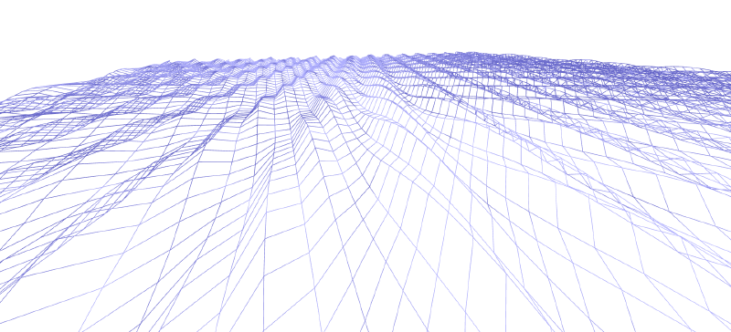
最终效果
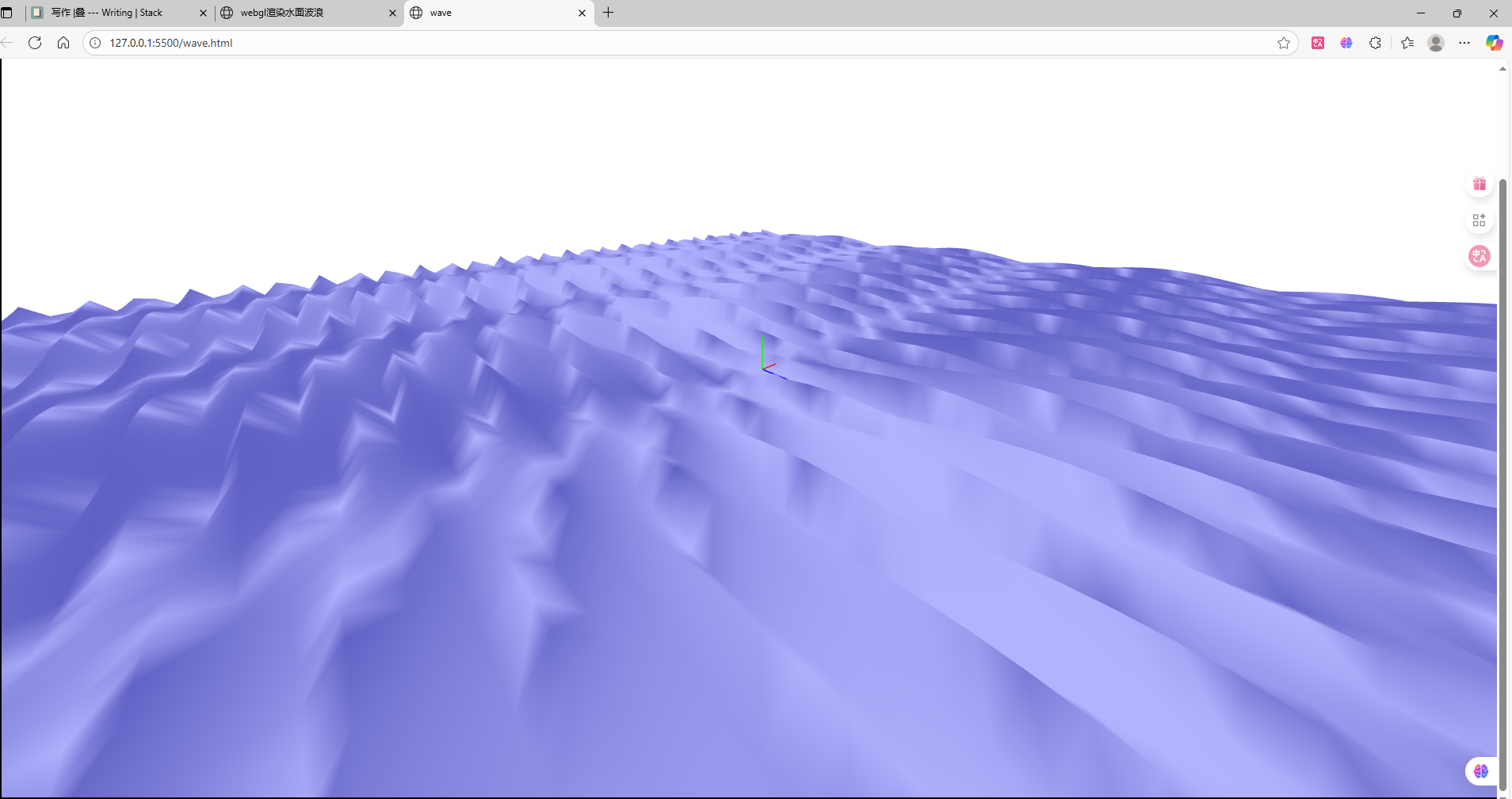 可以把plane的大小,旋转,细分,相机位置,观察位置和着色器中计算浪高的参数暴露出来,使用html的lable
和input修改来调整画面到想要的效果。
可以把plane的大小,旋转,细分,相机位置,观察位置和着色器中计算浪高的参数暴露出来,使用html的lable
和input修改来调整画面到想要的效果。
遇到的问题
变换矩阵计算
计算变换到NDC空间的矩阵是由从模型空间->世界空间->视图空间->透视裁剪空间三次变换。
分别使用modelMatrix,viewMatrix,ProjectionMatrix,乘在一起叫mvp矩阵。
写成式子应该是 $P\times V\times M\times vertexPoint$,顺序出错会导致变换出问题,看不到内容。
也有可能是计算各个矩阵时参数没有设定好,如使用glmatrix库,计算透视ProjectionMatrix,near和far参数应该是大于0的数,且far > near。
模糊问题
最开始在canvas属性的设置中,没看清代码,只设置CSSstyle中的width,height。
但是应该设置canvas的html属性,这个才是和分辨率相关的。CSSstyle的是画布的物理尺寸和分辨率无关。
1
2
3
4
|
//正确写法
<canvas id="glcanvas" style="border: 2px solid black;" width="1920" height="1080"></canvas>
//错误写法
<canvas id="glcanvas" style="border: 2px solid black; width: 100%; heigth: 100%"></canvas>
|
相关链接:
本文矩阵计算使用glmatrix。
webgl代码及代码组织学习自MDN Web Docs和webgl基础